IEEE CEDA / Taiwan MOE, ICCAD 2016 Contest
NP3: Non-exact Projective NPNP Boolean Matching
Chi-An (Rocky) Wu and Chih-Jen (Jacky) Hsu ,
Cadence Taiwan, Inc.
2F, No.6-5, Du Sing Rd., Hsinchu, Taiwan
I. Introduction
Boolean Matching [1,2] is one of the most widely-used engines in industrial applications and most widely-studied engines in academic research. Basic Boolean matching is for NPNP-equivalence, which negates (N) and permutes (P) circuit inputs and outputs to achieve circuit equivalences. In this contest, we extend the problem more closely to recent industrial challenges from two directions, Non-exact and Projective. The goal of non-exact is to achieve the largest number of output equivalences; projective extends the matching that allows grouping to match another design. Therefore, Non-exact Projective NPNP (NP3) Boolean matching is a problem to find input-groups of two designs for achieving maximum equivalent output-groups as shown in Figure 1. Beyond the basic NPNP Boolean matching, it could be used for achieving better quality and applied to related applications, such as library binding [3], synthesis [4,5], engineering change order [6,7], logic verification [8], and hardware Trojan detection [9]. In our application, the main issue is to find appropriate input-groups, so the number of circuit outputs in a circuit will be limited to 1~16 in this contest.

Fig.1 NP3 Boolean matching
In recent academic research, the methods of basic Boolean matching are developed in several approaches including structure-based, simulation-based, and formal methods [2-16]. Each approach has its own advantages and limitations. In our topic, NP3 Boolean matching is an extension of the basic one and can bring more significant values for research in next generation.
II. Contest Objectives
The objective of the contest is to develop a more flexible and powerful Boolean matching engine that can be widely utilized in industry tools. We will provide industrial benchmarks which can represent our challenging problems in diverse applications. We look forward to milestone ideas to achieve optimal matching and bring about new topics in this research area.
III. FORMAL PROBLEM DEFINITION AND INPUT/OUTPUT FORMAT
Given two combinational circuits, contestants need to find the matching groups of their inputs and outputs that will achieve the largest number of equivalent output groups. A matching group consists of corresponding merged inputs along with their phase, or the inputs which should be set to constants. For example, given two circuits in Figure 2, the first circuit has output functions $ \{ f_1=(a \land c),f_2=(a \lor (b \land c)) \}$, and the second circuit has output functions $ \{ h_1=(x \lor (-y \land z)),h2=(x \land u) \}$. In order to achieve the most equivalent output-groups, the matching groups could be $(a,x), (b,-y), (c,u,z), (f_1,h_2), (f_2,h_1)$ thereby achieving two equivalences$(f_1 == h_2)$and$(f_2 == h_1)$. However, if the matching groups are $(a,-y), (b,u), (c,z), (x=0), (f_1,h_1), (f_2,h_2)$, only one equivalence$(f_1==h_1)$is achieved.

Fig.2
In addition, there are some limitations for grouping:
- Every matching group can have only one input or output of the first circuit.
- Contestants cannot bind the inputs of the first circuit to constants.
- One circuit input/output can exist in at most one group.
Program Requirements
The requested program should run in a Linux system with a single thread (multiple threads or processes are not allowed). The time limit of running each test case is 1800 seconds in CPU time. The executable file should be named “bmatch” and accepts three arguments:
./bmatch <cir1.v> <cir2.v> <match.out>
<cir1.v> <cir2.v> are input files which describe a Verilog circuit individually. <match.out> is an output file where contestants answer the matching groups.
Input Format
<cir1.v> <cir2.v> is gate-level circuit which has only one module with primitive gates in Verilog. Notice that there may be same name token between <cir1.v> and <cir2.v>.
modeule <cir_name> ( <name0>, <name1>, … );
input <name0>, <name1>, …;
output <name0>, <name1>,…;
wire <name0>, <name1> , …;
<primitive gate type> ( <name0>, <name1>, … );
<primitive gate type> ( <name0>, <name1>, … );
…
endmodule
Output Format
<match.out> includes three kinds of matching groups: INGROUP, OUTGROUP, and CONST0GROUP.
- An INGROUP is the matching group of circuit inputs in both circuits. Its format is:
INGROUP 1 + <name0>
2 + <name1>
2 - <name2>
2 + <name3>
…
ENDThe first character of each line is “1” or “2” which means the circuit input is from <cir1.v> or <cir2.v>. The second character is “+” or “-“ which means positive or negative phase. The last string <name0> is the name of a circuit input. Here are some limitation rules for grouping.
- A group must include exactly one name of circuit input in
. For example, it cannot be: One INGROUP
1 + name0
1 + name1
2 + name2
END - One circuit input’s name can exist in at most one group. For example, it cannot be:
INGROUP
1 + name0
2 + name1
END
INGROUP
1 + name2
2 + name1
END
- A group must include exactly one name of circuit input in
- An OUTGROUP is the matching group of circuit outputs in both circuits. Its format is:
OUTGROUP
1 + <name0>
2 + <name1>
2 - <name2>
2 + <name3>
…
END
The first character of each line is “1” or “2” which means the circuit output is from <cir1.v> or <cir2.v>. The second character is “+” or “-“ which means positive or negative phase. The last string
is the name of a circuit output. Here are some limitation rules for grouping: - A group must include exactly one name of circuit output in <cir1.v>
- One circuit output’s name can exist in at most one group.
- CONST0GROUP is a group of binding <cir2.v> circuit inputs to constants. There can be at most one CONST0GROUP in <match.out>. Its format is;
CONST0GROUP
2 + <name0>
2 - <name1>
2 + <name2>
…
END
The first character is “2” which means it is in <cir2.v>. The second character is “+” or “-“ which means positive or negative phase to bind the constant. “2 + <name0>” is to bind
to constant 0.”2 - <name1>” is to bind <name1> to constant 1. Here are some limitation rules for grouping: - Only circuit inputs in <cir2.v> are allowed to be in this group. There cannot be any circuit input of <cir1.v> or any circuit output of <cir1.v> and <cir2.v> in this group. For example, it cannot be:
CONST0GROUP
1 + name0
END
- If one name exists in this group, it cannot exist in other groups (including an INGROUP and an OUTGROUP). For example, it cannot be:
CONST0GROUP
2 + name0
END
INGROUP
1 + name1
2 + name0
END
- Only circuit inputs in <cir2.v> are allowed to be in this group. There cannot be any circuit input of <cir1.v> or any circuit output of <cir1.v> and <cir2.v> in this group. For example, it cannot be:
IV. Evaluation Methodology
In this problem, matching pairs between two designs are most important. Merging outputs and efficiency are the secondary considerations. Hence, we design an evaluation methodology as follows.
The score of each case is calculated based on the scores of OUTGROUPs. If an OUTGROUP has any non-equivalence, there is no score for this group. If circuit outputs in OUTGROUP are all pair-wise equivalent, the score is 10 + N where N is the number of circuit outputs. The summation of the scores of output groups is the score of this case. The summation of the scores of all cases is the score of your result. The team with the highest score wins the contest.
For example, given a in <cir1.v> and x, y in <cir2.v>, $a == x == y$. The matching group $(a,x)$ can get a score 10 + 2 = 12. The matching group $(a,x,y)$ can get a score 10 + 3 = 13. However, if $a \neq y$, the matching group $(a,x,y)$ will get a score 0, but the matching group $(a,x)$ still get a score 12.
If two teams have the same score, the rank will be decided by the total runtime of all cases. If a case runs longer than the time limit of 1800 seconds and there is no
V. Example
Given a case with two designs:
| cir1.v | cir2.v |
|
module top( a, b, c, g, f, h ); input a, b, c;, output g, f, h; and ( f, a, b ); or ( h, a, c ); xor ( g, f, h ); endmodule 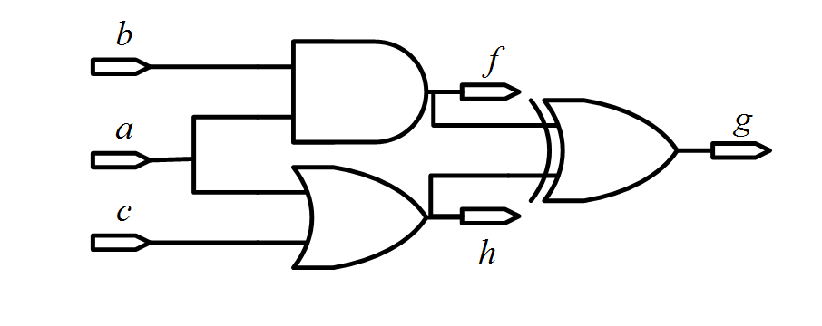
|
module top( s, t, u, v, w, x, y, z ); input s, t, u, v, w; output x, y, z; wire tn; not ( tn, t ); and ( x, w, v, tn ); or ( y, w, u, tn ); xor ( z, y, s ); endmodule 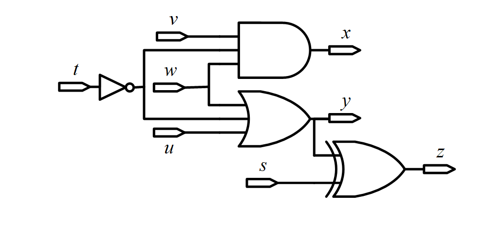
|
Team A:
| match.out | ||
|
OUTGROUP 1 + f 2 + x END OUTGROUP 1 + h 2 + y 2 - z END |
INGROUP 1 + a 2 + w 2 - t END INGROUP 1 + b 2 + v END |
INGROUP 1 + c 2 + u END CONST0GROUP 2 – s END |
$t$ is negatively grouped with w, and s is bind to constant 1, so$f==x$and$h==y==-z$.
The score is (10+2) + (10+3) = 25, where(10+2) is from $f==x$ and (10+3) is from $h==y==-z$.
Team B:
| match.out | ||
|
OUTGROUP 1 + f 2 + x END OUTGROUP 1 + h 2 + y END |
INGROUP 1 + a 2 + w 2 - t END INGROUP 1 + b 2 + v END |
INGROUP 1 + c 2 + u END |
$f==x$ and $h==y$ are correct.Hence, Team B gets the score (10+2) + (10+2) = 24.
Team C:
| match.out | ||
|
OUTGROUP 1 + f 2 + x 2 + z END OUTGROUP 1 + h 2 + y END |
INGROUP 1 + a 2 + w 2 - t END INGROUP 1 + b 2 + v END |
INGROUP 1 + c 2 + u 2 - s END |
$f==x$ and $h==y$ are correct, but $f==z$ is incorrect.Hence, Team C only get score 12 from $h==y$.
Team Ranking:1. Team A ( score 25 ) 2. Team B ( score 24 ) 3. Team C ( score 12 )
VI. Problem Guidance
At the start, we suggest contestants write a simple Verilog gate-level parser to put designs into proper circuit structures so that a Boolean matching engine can be developed based on such circuit structures and output <match.out>. Contestants are encouraged to brainstorm for new ideas. For a tutorial and an overview of current algorithms, contestants are advised to survey the course slides [1], the book chapter [2] and the papers related to [16].
For old basic Boolean matching, there are some academic papers developed in various aspects: Spectral [3], Signature [2,10,11], Canonical-form [12,13], BDD [3,8,14], and SAT [2,11,15,16]. Notice that they are just for reference and cannot be directly applied to this new topic. Besides, some circuit cases may be too large to be directly represented by BDDs. We encourage contestants to try some new ideas. Your program should generate
Finally, have fun and welcome to submit questions.
VII. Reference
[1]Hadi Katebi and Igor L. Markov, Large-scale Boolean Matching, DATE, 2010
[2]TingTing Hwang, “Boolean Matching in Logic Synthesis”, course slide.
Ahttp://www.cs.nthu.edu.tw/~tingting/logic/ch5-2.ppt
[3]Luca Benini and Giovanni De Micheli, A Survey of Boolean Matching Techniques for Library Binding,Design Automation Electronic System, ACM, 1997.
[4]J. Cong and Y.-Y. Hwang, Boolean Matching for LUT-Based Logic Blocks with Applications to Architecture Evaluation and Technology Mapping,
CAD Integrated Circuit System, IEEE, 2006.
[5]C. Yu, L. Wang, C. Zhang, Y. Hu, and L. He, Fast Filter-Based Boolean Matchers, Embedded Systems Letters, IEEE, 2013.
[6]S. Krishnaswamy, H. Ren, N. Modi, and R. Puri, DeltaSyn: An efficient logic-difference optimizer for ECO synthesis, ICCAD, 2009.
[7]S.-L. Huang, W.-H. Lin, C.-Y. (Ric) Huang, Match and replace - A functional ECO engine for multi-error circuit rectification, ICCAD, 2011.
[8]J. Mohnke, P. Molitor, and S. Malik, Application of BDDs in Boolean matching techniques for formal logic combinational verification,
Software tools for Technology Transfer, 2001.
[9]P. Swierczynski, M. Fyrbiak, C. Paar, and C. Huriaux, Protecting against Cryptographic Trojans in FPGAs, FCCM, 2015.
[10]A. Abdollahi, Signature based Boolean matching in the presence of don’t care, DAC, 2008.
[11]K.-H. Wang, C.-M. Chan, and J.-C. Liu, Simulation and SAT-Based Boolean Matching for Large Boolean Networks, DAC, 2009.
[12]G. Agosta, F. Bruschi, G. Pelosi, and D. Sciuto, A Transform-Parametric Approach to Boolean Matching, CAD Integrated Circuit System, IEEE, 2009.
[13]Z. Huang, L. Wang, Y. Nasikovskiy, and A. Mishchenko, Fast Boolean matching based on NPN classification, ICFPT, 2013.
[14]S. Chatterjee, A. Mishchenko, R. Brayton, Reducing Structural Bias in Technology Map, ICCAD, 2005
[15]C.F. Lai, J.-H.R. Jiang, and K.-H. Wang, BooM: A Decision Procedure for Boolean Matching with Abstraction and Dynamic Learning, DAC, 2010
[16]C.F. Lai, J.-H. R. Jiang, and K.-H. Wang, Boolean Matching of Function Vectors with Strengthened Learning, ICCAD, 2010
VIII. Test Case
IX. Beta Test

X. FAQ
- Do the benchmarks always have the same number of outputs?
No, we don't assume this. Benchmarks may have different number of outputs. -
What is the maximum number of input size and total gate count?
The maximum number of input size and total gate count is 1000000, and real provided cases will be much smaller than this number. -
Can I have an input in Circuit 1 that is not matched by any input in Circuit 2? That is, will there be any redundant inputs in Circuit 1?
Yes, inputs can be non-matched. There may exist extra redundant inputs. -
For output convenience, can a matching group be empty? For example:
INGROUP
1 + name0
END
or
CONST0GROUP
END
It is OK to be empty for a matching group. -
I think the first example in "Output Format" section has a typo: "One INGROUP" should be "INGROUP".
Yes, it should be “INGROUP” in the example. “One” is redundant. -
I am reading the problem guidance of problem B. But I found that there are mismatchings between the guidance and the reference list. Contestants are advised to survey the course slides [1], the book chapter [2] and the papers related to [16].
Yes, the reference should be “the course slides [2], the book chapter [1]”. -
Are we allowed to use code written by others, like libraries released under MIT license?
Yes. Any library is allowed. -
What are all the possible gate types (and, or, xor, etc.) in the circuit?
All gate types are in Verilog primitive gate types: and, nand, or, nor, xor, xnor, buf, not. -
When the parser read cir2.v in case3, we find that in the 208 209 and 215 line of this benchmark, there is no space before ')'. But in other cases of benchmarks, there isn't such space problem. There are also some other places in this circuit lack of spaces. Is it a bug for this benchmark, it won't appear in the test, or our parser need to distinguish this and do continued?
line207: buf ( n248 , n9999 );
line208: buf ( n530 , PI_PI_clock);
It is not bug and not difficult to parse. Of course, it matches our problem formulation and Verilog format. -
Is multi-thread allowed in the evaluation?
No. We limit the program in single thread. -
What do you mean by redundant? Does it mean redundant to all of the outputs?
If you mean "redundant input", it means that changing its value doesn't affect outputs' functions. It may be only redundant to some of the outputs. -
The webpage of problem B says that the name of the executable file should be "bmatch", but the email says the name should be same as the registration number. What name should we use?
Please follow the pdf of “2016 Alpha Test Announcement_Problem ABC”. Use the register number of your team (e.g., “cada001”). -
I noticed that both problem a and c have released the ranking of alpha submission. Will there be any ranking information of problem B?
No. In alpha submission, we make sure that contestants can submit valid program and correct output format first. -
Will case0~case17 be tested in the final test? Also, are there other hidden testcases?
- Yes, case 0~case 17 will be tested in the final test. Their score will be included in the final score.
- Yes, there will be some other hidden testcases.
-
What is the memory limit for each cases?
The memory limit is 32GB. -
If both teams get no answer for a test case, how to count the running time?
The runtime is calculated by when your program finish. It does not depend on the answer. Besides, if your program crash or timeout, the runtime is evaluated to be 1800 seconds. -
How does the runtime influence the final result? As you say, if the total score is same, you will check the total runtime. If we know we can not obtain a result for some cases, we will stop the program(not crash). Then the total runtime for these cases is short. Or we can let it run. Then the total runtime is 1800 *n, where n is the number of cases that we can not obtain the results. but it may be not fair. Will you consider a weighted sum score? A case with score x and runtime y will get a score like x/y? Or will you treat all cases with score 0 as runtime 1800?
No change. If two teams get same score, the one with shorter runtime is better for efficiency. If you can develop some heuristics to stop, another team also can. Remember there are some hidden cases, and heuristics will also affect hidden cases.